LED Pin: Displaying the stats on a wearable, Part II
April 15, 2016 |
Last week I showed how to deploy a Node-RED application that analyzed the tone of tweets using the Watson Tone Analyzer. The results were displayed on a webpage. In this blog post, we’ll connect the Node-RED application to the Watson Internet of Things Platform and control a NeoPixel LED ring powered by an Arduino compatible Particle Photon board.
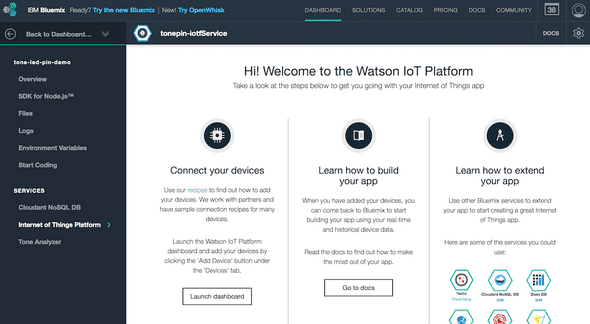
First we need to register a new device with the IoT Platform. In the application overview in IBM Bluemix, click on the Internet of Things Platform service tile.
Click on the Launch dashboard button at the bottom of the first column.
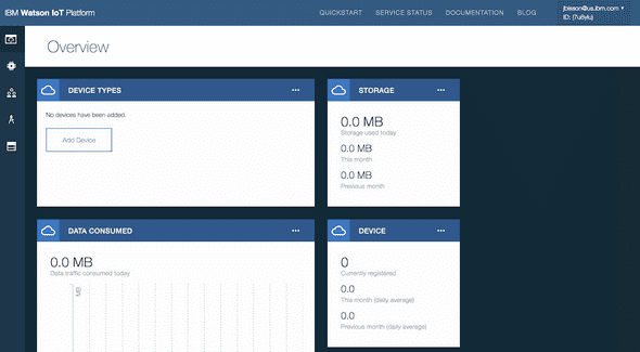
This is the IoT Platform dashboard where you can add and remove device types and devices, get API keys, and view data and events that pass through the service.
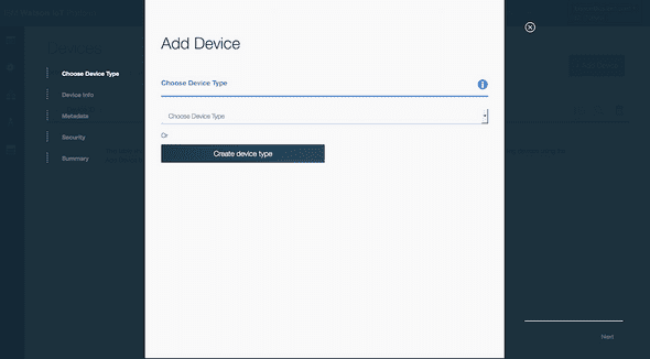
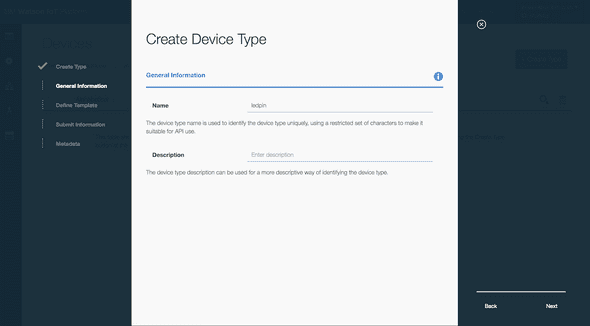
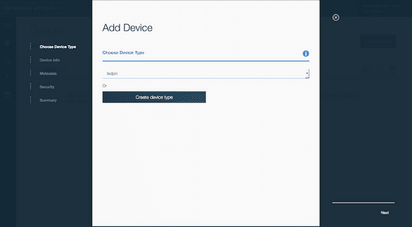
Click on the Add Device button. We first need to create a device type, which is basically a named type for similar devices. I’ve chosen to use ledpin, but you can choose whatever you want. Skip through the rest of the steps until you return back to the Add Device screen with the new device type listed in the drop down menu. Select the device type that was just created and click Next to add a single device.
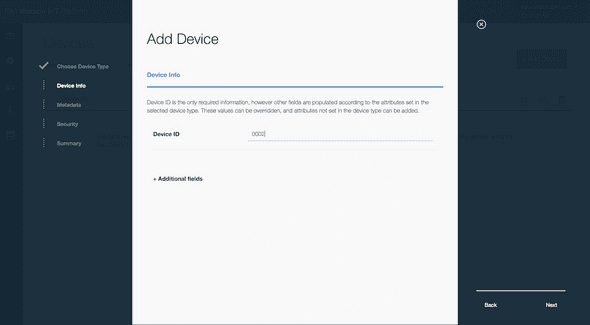
Now we’re going to get specific to a single device, of type ledpin. Enter a unique ID for this device. If you add another pin in the future, it will have the same type ledpin, but with a different Device ID. This way, each device has separate data streams and can be accessed individually.
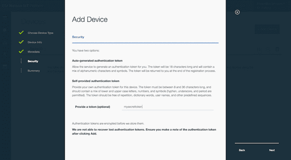
Skip to the screen where you can choose a token. You can choose a specific token that is used when authenticating the device to the IoT Platform service. Or, leaving this blank will generate a randomized token (similar to a password).
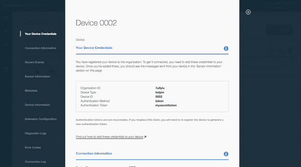
The final screen will show the credentials necessary to connect the device to the IoT Platform service. Keep this info handy as the token is only shown once.
Configure Node-RED to publish the statistics
The next step is to configure the IoT nodes in Node-RED to send the device the statistics when two events occur:
- when the pin connects to the IoT Platform service
- once a minute when the last minute stats are updated
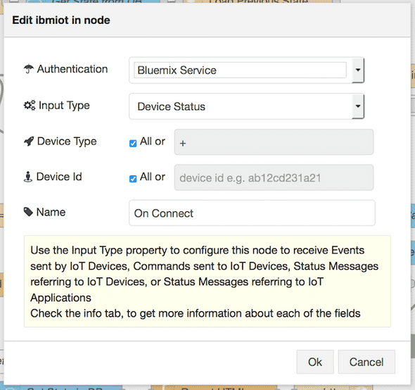
Add an ibmiot in node on the left side, and add an ibmiot out node on the right side of the flow, connecting them together as follows:
In the ibmiot in node, enter the device type and device ID from the Watson IoT Platform service.
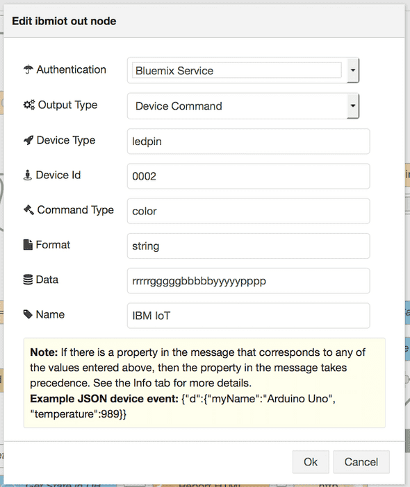
In the ibmiot out node, enter the Device Type, Device ID values from the Watson IoT Platform and the remaining values as shown below:
Click on the Deploy button in the top right corner of the page to save and deploy the changes.
The LED Pin hardware
For the hardware, I used a Particle Photon and a NeoPixel Ring with 24 LED lights.
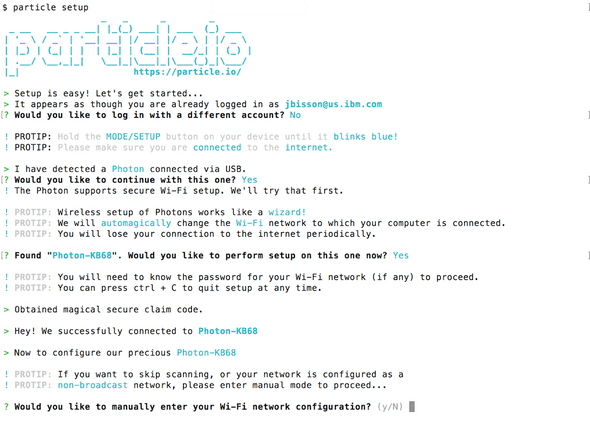
Sign up for an account on the Particle.io website, sync the device via USB and the command-line interface.
This process makes it quick and easy to write Arduino code in the web browser IDE and deploy it to the device (called flashing the device).
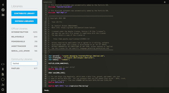
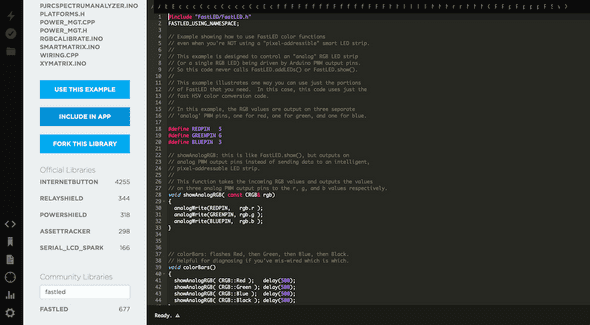
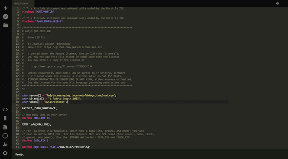
You can find the Arduino code in my GitHub repo. Copy the contents of the main.ino file into the web IDE. There are two libaries that need to be included in the application. Click on the Libraries icon in the left sidebar. Search for the FASTLED library. Click on the search result. Scroll down and click on Include in App.
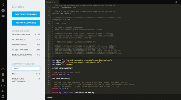
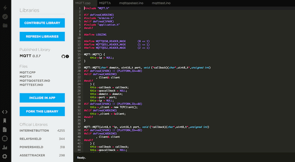
Repeat this process for the MQTT library.
Finally, copy the device credentials created earlier in the Watson IoT Platform service and replace the following:
- <orgid> with the Organization ID
- <deviceid> with the Device ID
- <token> with the authenication token
Click on the Verify button in the left sidebar to confirm the code compiles. Then click on the Flash button in the left sidebar. The code will be pushed to the LED pin.
The pin should change colors when it restarts and connects to the Watson IoT Platform service successfully. After a minute, the LEDs may change colors, dependent on the activity of the Twitter search.
How does pin change color?
When the pin connects to the Watson IoT Platform, or when the Node-RED application updates the last minute stats, the pin receives a message in a format like:
rrrrrgggggbbbbbyyyyyppppThis message instructs the pin to color each LED light a specific color. In the above example, the first five LED lights are colored red, the next five colored green, the next five colored blue, the next five colored yellow, and the last four colored purple.
Here are a couple of modifications that you can tinker with:
- change the pattern of the LEDs displayed on startup: change the Data textbox in the ibmiot out node
- change the colors of each tone category: double click on the Customize Settings node and change the colors in the pinColors property
- add new colors on the LED pin: add new case statements in the switch statement located in the callback function
What else can you represent using 24 LED pins? You can expand this application to toggle between different modes, just by pushing new messages via the Watson IoT platform to the pin. The possibilities are practically endless.
Congratulations! You made it through a gauntlet of social media, Cloud services, and hardware to create your very own LED pin and website showing the tone from tweets on Twitter.
